Patch Detail Pane

Adding Other Information
In addition to the “Fixture #”, “Patch Address” and “Fixture Make/Model” columns, the Patch Detail pane allows more information about the patch to be stored. Some of the fields directly influence the output of the channel while others are used for reference to help program your show.
NEO Notes & Tips: The following lists all the additional columns that could be displayed in the default order. The columns that are visible, their widths and their positions in the grid are customizable by the user.
P/T Adjust
These options give you the ability to reverse the operation of the pan and tilt control of moving lights. If you find that a moving light has been hung in reverse to the logical movement of the light, then you can correct it without having to physically change the position of the light. Use the drop-down combo to select the adjustment you want.
Flip Pan – The pan function of the fixture will be reversed.
Flip Tilt – The tilt function of the fixture will be reversed.
Flip Pan & Tilt – The pan & tilt function of the fixture will be reversed.
Swap Pan & Tilt – The pan function will operate tilt and the tilt will operate pan.
Profile
Use the drop-down combo box to select the default profile for the channel. See Edit Profiles below for more information about this option.
Defaults
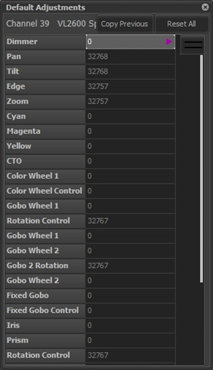
When a fixture is patched, the default values of its attributes are determined by the values read in from the fixture library. This field allows you to change the standard defaults on a fixture by fixture basis. The following screenshots show an example of changing the defaults for a patched fixture. To see the list of attributes and their current values, click on the Defaults box of the desired fixture:
Next, click on the attribute value (right hand column) whose default you wish to change. For this example, the default position will be set by clicking on either the value of Pan or Tilt. To help you set the correct default value(s), any Groups or Palettes stored in the show file will be displayed as shown below:
Since in this example we’re setting the default position, select the Position tab to display palettes that have position information and click on the desired default, such as “”. The resulting values for Pan & Tilt are shown below:
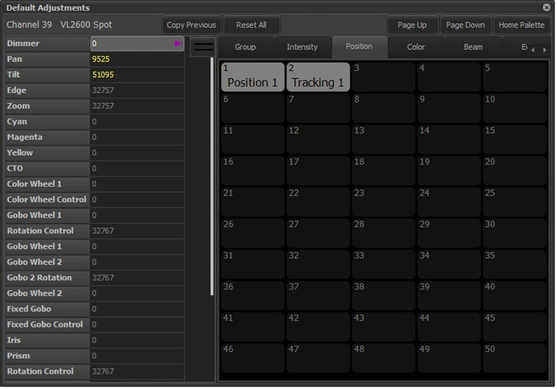
Any values read in from the palette will be shown in yellow. You can also select an attribute and enter a value manually.
A special palette called the “Home Palette” can be defined in the Groups Editor and accessed by clicking the Home Palette button. The attributes of the target fixture can be returned to their original default values by clicking on the Reset All button.
Defaults may be set and reset also via the “Command Line Method”. The syntax of the commands is:
{channel list} SET DEFAULTS {palette type} {palette ID}
{channel list} CLEAR DEFAULTS
Example:
37/40 SET DEFAULTS COLOR 5 <RETURN> - Set the color defaults of fixtures 37 through 40 to the values stored in color palette 5.
Aux Dimmers
Some fixtures require a separate DMX address for dimmer control. The Vari-Lite VL5, for example, does not have the dimmer included in the list of control channels. This is because the dimmer is a separate power feed to the fixture. The Aux Dimmer column can be used to set the address of the external dimmer for this type of fixture.
Use this option when working with color scrollers where the dimmer is not located at a fixed distance from the control channel.
You can enter any list of dimmers required into this field.
Relay
LED, moving light and other intelligent fixtures require non-dimmable power for their operation. This power is sometimes supplied by adding or replacing standard dimmer modules in a lighting rig with special relay modules that can switch the power on and off. Like “Aux Dimmers” above, this column can be used to associate the address(es) of the relay module(s) supplying power to the fixture(s) patched to the selected channel(s). Addresses entered in this column will be labelled “Relay” in the “DMX Outputs” section of the patch window and be set to an “Inverse Non-Dim” profile. When NEO is started, these DMX outputs will be set to “full”, meaning the relays will be energized (i.e. “Power On”).
There are user-settable options that can be set to control the operation of these relays. See System properties>System Settings>Intermediate for more detail.
Vis Patch
NEO supports having a separate patch for the visualizer output. If nothing is set in this field the software will default to the same patch information shown in the “Patch Detail” column and the information will be displayed in a light grey color.
To change the visualizer patching for any channel, simply edit the data in the same way as the “Patch Detail” column.
To return the visualizer patching on individual channels to the default, simply delete the contents of the field. As soon as you press <ENTER>, the default information will be displayed in a light grey color. To reset the entire visualizer patch, select Clear Patch -> Clear Visualizer Patch from the Options menu.
Position
Use the position field to describe where the fixture is located in the lighting rig. This field will be displayed in the channel grid for some views and is also added to the Quick Select Bar and Select Pulldown Menu.
Unit #
The unit number can be a number that stays with the fixture. Use the unit number field to store any number you find useful to identify the fixture.
Purpose
The purpose field should describe what the fixture is being used for. For example – “General Wash”, “Actor Special”, etc. This field will be displayed in the channel grid for some views and is also added to the Quick Select Bar and Select Pulldown Menu.
Color Description
The color description field can hold any text you want to describe the color filters that may have been added to the light. This field will be displayed in the verbose view of the channel display.
Color
The color field is used for a real-world representation of the color used in the fixture. This color will be shown in the channel display for easy reference. To set the color you can type any known color description (e.g. Red, Yellow, RE202, L194) into this field. If the color description is not known, then the color will be set to “None”. You can also select the color from the standard NEO color chooser by clicking on the button to the right of the field or by double clicking on the field. This field will be displayed in the channel grid for some views and is also added to the Quick Select Bar and Select Pulldown Menu.
Fixture Type
The fixture type field will be populated automatically by patching a fixture from the library. The fixture type is referenced to determine the symbol used in the layout (magic sheet) view for the channel. This field is read-only except for those channels patched to a “Standard Dimmer”.
The default Fixture Type for “Standard Dimmer” is ELLIPSOIDAL, however a pulldown list of other types is available to allow a better description of the kind of fixture patched to a given address to be chosen. Examples are: FRESNEL, PAR, PRACTICAL, etc.
Power
The power field will be populated automatically (if available) by patching a fixture from the library. This field should show the power consumption of the light.
Weight
The weight field will be populated automatically (if available) by patching a fixture from the library. This field should show the physical weight (in Kg) of the fixture.
Circuit Name, Circuit # & Dimmer Phase
Use these fields to record the power source to the fixture. This information may be needed later to debug power problems.
Accessories
If the fixture has any accessories added to it (top hat, barn doors, etc.), the information can be recorded into this field.
Generic Data 1, 2, 3
Any other information you want to record with the fixture can be stored in any of the three generic fields. Information in the “Generic 1” field will be displayed in the channel grid for some views and is also added to the Quick Select Bar.
VN Areas, VN Rooms, VN Channels
Information pertaining to Philips Strand VisionNet. See the Strand Lighting website for more information.
DMX Setting
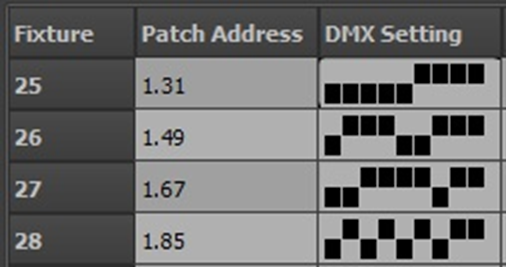
The DMX settings column is a read only display of the dip switch settings for the patched address. If the fixture’s address is set by dip switches, then this field can be used as a handy reference.